Notes On Rebuilding A TA Engine
"God should smile on people prepared to save MPJG engines!"
Jeff Redman - Australia
Much has been said about the shortcomings of the MPJG. Most coming from people who repeat what they’ve heard and not by owners or people who have actually maintained or rebuilt these engines. A TA with an MPJG maintained in good running order will not be straggling behind a TC in standard tune ...whether on an incline or straightaway. Those who know the issues with the MPJG will agree that the iron castings were not of the best quality and were also too thin in some places. (No antifreeze in prewar UK equals cracks in the block if water is allowed to freeze there!) That is where the problem lies and not with the function of engine itself. It was an outdated design even in 1936. And the head would have been stressed less had cylinders #2 and #3 not shared an exhaust port. But still, as said above, in good condition they’re a most reliable engine.
And - an honest M.G. TA has a correct and proper engine.
What follows in this site is my experience with installing a billet crank into my MPJG engine and tips from others on dealing with particular issues they’ve faced or overcome with their MPJG/M/W engined TAs.
After several thousand miles in my ownership and no telling how many thousands before me, the engine was tired. It was in need of new bearings, attention to the lifters, rocker shaft and bushings, valves, seats and guides, new cork in the clutch, timing chain, etc. etc. The original non-counterbalanced crank was/is in good condition and could have been used. But the balanced crank and Carrillo-type rod set came available, was too tempting and the adventure began.
These notes, ideas and comments are intended as notes only. And not a comprehensive how-to on rebuilding an MPJG engine.
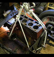
First we need to take the engine out.
ENGINE REMOVAL
Most of us probably remove the gearbox along with the engine but one friend who's done this many times finds it easier to separate the two and remove only the engine.
Here's what he has to say: "I normally take the engine out on it's own, so no need to disturb the interior and the gearbox. The only thing one has to remember is to put a container (catch pan) under the flywheel housing when you split this from the bell housing!! Also before removing the bolts from flywheel/bell housing remove the clutch operating arm from the shaft on the bell housing, by drifting out the dowel pin and prising the arm off the shaft (don't loose the woodruff key). If you don't do this first, you will not be able to separate the engine from the gearbox! Support the underside of the gearbox, and remove the two front rubber engine mounts from the chassis to give clearance to get the engine out."
Items such as the bonnet and radiator along with any other easily removed ancillaries would, of course, already have been removed.
Another friend used this method:
| 1. Disconnect battery then remove seats, carpets, floorboards, prop shaft tunnel. Undo end clips of bonnet and lift off (place on carpet somewhere). 2. Remove gearbox remote (take care of 3 springs & balls at rear), disconnect front of prop shaft and speedometer drive from gearbox. Loosen gearbox support bolting. 3. Disconnect exhaust pipe (including support to underside of bell-housing) and starter cable. 4. Remove dynamo, oil filter & pipe (precaution), oil gauge pipe, distributor to coil wire, oil gallery pipe to cylinder head. 5. Remove carbs, inlet & exhaust manifolds, drain radiator & block then remove rubber cooling hoses, petrol pump (for clearance), cylinder head and rear two cylinder head studs (again, for clearance). 6. Undo locking nuts under radiator, remove large bolts holding headlamp supports to radiator cross member. Protect headlights then lift out radiator assembly. 7. Undo front engine mounting bolts, put engines slings under front of oil sump and rear of same. 8. (Two people are best from here on) Using two chain hoist on beam (sufficient to carry up to 5 cwt), take engine weight then remove front engine mounting bolts and gearbox mounts. 9. Release handbrake, slowly roll car back while lowering rear sling, then start lifting the front sling to clear the chassis. Eventually, nearing 45 degrees, it will be possible for the gearbox to clear the underside of the foot ramp and roll the car further while easing out the engine/gearbox. 10. Once clear of the rolling chassis lower the engine assembly onto a trolley, preferably fitted with a box support to the sides of the sump (not the base as this is weak). |
It really isn't all that difficult or time consuming to remove the seats and floor boards. And it gives easy access to the drive shaft and transmission mounts as well as allowing a good visual check on the condition of everything else under there. But it is also nice to know that IF you want to remove only the engine it is possible. Don't forget the catch pan!
MATING THE TRANSMISSION/BELL HOUSING BACK TO THE ENGINEL
This may seem a little early in the ‘rebuild’ process, but when the time comes to join the transmission and engine (assuming they’ve been removed and or separated) there’s a procedure that must be followed with regard to the forks on the throw out bearing. Because the TA throw out bearing and pressure plate does not function in the same manner as most dry clutch applications, understanding how they go back together is imperative! There’s a detailed explanation on the Clutch/Flywheel Page under the heading Mating The Transmission/Bell Housing To The Engine.
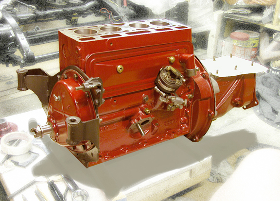
The MPJG - Rebuild in progress.
No, the engine mounting plate was not painted a different color! It was originally the same engine red.
Here and elsewhere on these pages I candidly point out a number of known weaknesses (as well as strengths) of the MPJG engine which might lead to the question; Are these engines worth the effort and expense of rebuilding? The answer is, of course, an emphatic (subjective) Yes!
The youngest of these is now over 80 years old, most are likely to have seen many years of use and abuse and replacement parts are increasingly difficult to find. Keep in mind the TA with its MPJG is a Pre-War car. The TA’s engine was based on technology of the 1920’s having evolved from older, side valve, Morris designs and we know for sure there should have been more meat in the deck. And there’s been a long held rumor that the castings were of poor quality iron but we’ve never seen any factual data backing that up. Even if some castings had been of questionable quality is the MPJG a ‘bad’ engine? No, even when the design faults are taken into consideration, if used sensibly it’s actually a very reliable and extremely forgiving engine. It is NOT a high revving engine. Too many of these poor ole lumps were clapped out and run into the ground because of negligent service and shoddy maintenance. That’s a fault of the owner, not the engine. And a proper TA has an MPJG engine. With that to dwell on I’ll continue...

Repaired Block
Most of us aren't old enough to remember, but anti-freeze, prior to WWII, was not generally available. And on nights when the temperature was expected to drop below freezing the water had to be drained from engine and radiators else they could be destroyed by the expanding ice. The MPJG block above may have suffered that fate. Some engines survived and continued running with the help of a brass plate 'sewn' to the side of the block. This one did, for a year or more after a major rebuild, till oil was found to be seeping into the water jacket. Sadly it has now been retired. Replaced with an MPJM Morris block.

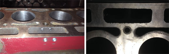
Where A Stud Pulled Out Of The Block
Extra care must be taken when ‘torquing’ down the cylinder head because there's just not a lot of deck into which some of the studs are threaded. And with years of cleaning up and 'decking' that surface gets thinner and thinner. It is not unusual to hear of someone pulling a stud right out of the block and sometimes breaking out a section of the water jacket as well. Therefore when replacing the studs be sure the threads have been cleaned using a tap and then coat the threads well with a good gasket sealant.
Tim Parrott photos
Block Repaired Where Stud Pulled Out
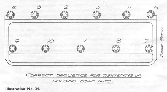
Sequence For Tightening Head Nuts - Illustration from the Instruction Manual
Torque?
While on the subject of blocks and heads, torque values are always wished for only to be told there were none. Philip Smith's humorous advice was to 'tighten the head nuts using a 6 inch ring-spanner and apply "with the strength of an average man" plenty of force'. More modern notes from Brian Rainbow, UK, suggest "..after fitting hardened washers over the studs (coated with a bit of oil) bring the nuts down finger tight. Then torque nuts down to 10 lb/ft in correct sequence, then increase in 5 lb/ft steps until max of 30 lb/ft is reached. This is necessary because it is all too easy to pull the studs out, particularly on # 1, 9 and 10 as these have only about 0.25 inch head deck thickness."
One other note on torque; when I asked what numbers he'd used to torque the head on his TA Tickford, an owner in OZ said "..I must say we were VERY cautious with head stud tensions when the
'deck' of the block was noted. THAT's scary, and my notes show we were
10ft/lbs LESS than XPAG."
With our low compression engines all we really need is enough to adequately clamp the head gasket. I've gone well above 35 lb/ft (prior to having this knowledge!) but I'm much more cautious now and try to keep it near that figure.
And this is probably a good place to put in a USE AT YOUR OWN RISK disclaimer. While I've tried to be as accurate as possible with descriptions, number, quotes and details there's bound to be something screwy in here somewhere. Right? So.. Neither I, nor any other author, contributor, rascal, or anyone else connected with this site, in any way whatsoever, can or will be held responsible for how you use the information contained in or linked from these web pages. Furthermore and on top of that all the bits here, either attached or falling off, are © copyrighted - too!
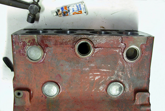
Careful When Installing Core Plugs
The area of the casting around the core plugs in the block is vulnerable as well. And it is now suggested not to hammer core plugs flat, as is the usual practice on 'modern' engines, but to epoxy them into place then seal them on the outside with gasket sealer. Another precaution suggested to me was to apply a thin layer of solder around the circumference of the core plug before fitting, giving it a 'soft' contact against the block and possibly reducing electrolysis. And for longevity some rebuilders paint the inside of the core plug with Glyptal paint before installing them. I did use a hammer to tap them just enough to bite the block (gasket sealer already in place) and then cleaned up the edges and added epoxy (JB Weld) around the perimeter before painting.
Some have addressed the porosity issue with these castings by having the block and the head ceramicly sealed or impregnated using resins. (I did nothing inside the water jacket of the head or block but did paint the inside of the block and sump with Glyptal.) Locating a good MPJG replacement block is not easy or cheap. If all hope of finding a TA block is lost then one might find an MPJM (Morris) or MPJW (Wolseley) engine block in the UK or OZ where they were more plentiful. These were virtually the same blocks and there were lots more Morris cars manufactured than M.G.s!

Markings Identify The Wolseley & Morris Cylinder Head
MG Head Was Marked [ 10 G ] here.
Good cylinder heads are also hard to find, most have been skimmed several times and they are prone to crack if allowed to overheat. But these too may be substituted by using Wolseley or Morris 10 heads. The question of whether or not to cut a head and install hardened seats is always a topic of discussion among TA owners. I chose not to install hardened seats and used a lead substitute for the first thousand miles or so but have not kept up that practice. I do, however, run a bit richer fuel mixture than normal. There's also the question with the early models of using double or triple valve springs. Most now prefer the triple spring set which the later MPJG engines used. But new double spring sets should not have the problems with breaking as a few people experienced back when these engines were new. If switching from dual springs to tripple remember to source the base and caps too as the ones for dual spring won't work with the tripple spring set up.
Original Cylinder Head Depth
I am informed that the original thickness of an MPJG cylinder head was 3 25/64 inch thick (3.390").
According to Philip H Smith; p73 - The head can be shaved to increase the compression from the original 6.5 to 1 to 7.3 to 1 without ill affects using pool fuel as long as the car is driven 'intelligently and not expected to slog. "This ratio is obtained by machining off sufficient metal to give a head depth of 3.292 in. (stage 2) instead of 3.386 in., or, strictly speaking, 0.094 in. However it is much simpler to request the machinist to plane off 0.1 in., and the difference is negligible." He goes on to say that that increase is worthwhile but one shouldn't go farther else rapid bearing wear will occur. Further he says that in 1938-9 some TAs achieved ratios as high as 8 to 1 using special fuel and counter balanced shafts.
Std. head depth = 3.386 inches OR 3.390 inches depending on the source. And there's not enough difference to quibble over!
Also remember this; if you are skimming a head, the proper way to get the correct rocker angle when using a skimmed head is to shorten the push-rods. If you put spacers under the rocker pillars to compensate for head skimming, you end up with an incorrect rocker to valve operating angle. The rocker will not swipe the valve correctly and will end up with excessive valve and/or guide wear.
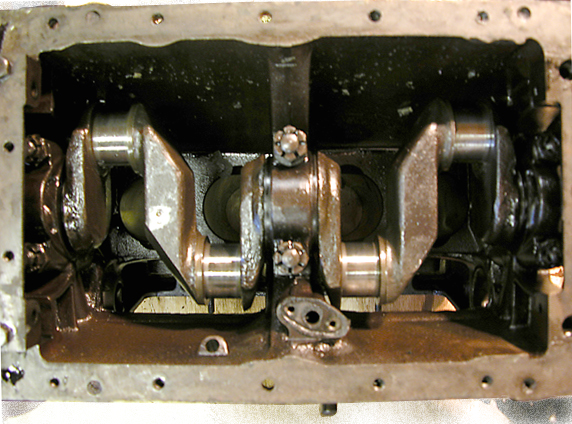
Original Non-counterbalanced Crankshaft
The original MPJG used a non-counterbalanced crankshaft. While they are quite serviceable, they can add a bit of stress and unwanted vibration into the block unless all the moving parts are balanced. So it's only common sense to have the crank, and everything subject to rotating inside the engine, balanced. And, after all these years of use, some of our original cranks are likely to be turned to the maximum safe undersize. However, one of the strong points of the MPJG is that by using babbitt (white metalled) bearings, standard regrind dimensions are nonexistent. One can remove the least amount possible from a journal to clean it up and then have the babbitt sized to that journal. Nor do all the journals have to be the same dimension. Just be aware of the balance problem and try to keep everything within reason.
The main bearings used in the MPJG engines have a very thick shell onto which the babbitt is poured. They’re similar to modern shell bearings but are much more robust because of their thickness and the babbitt. Once they’ve been re-babbitted they will need to be placed into the block and main bearing caps, tightened down and then align bored. This is usually carried out by a machine shop or engine builder and is necessary to assure that the crankshaft doesn’t bind in one of the sets.
Shims: These engines did not come with shims between the big end caps of the rods. However here’s a thought if you are about to have new babbitt poured and intend to use the engine for high mileage. When I first opened the sump on TA2190 back in 1974 I found two or three shims on each side between the rod and cap of the big ends and not knowing any better I assumed all TAs had that ‘feature’. As the years and miles racked up I would check the rod clearance ever so often and if need be I’d remove a enough to bring the gap to a reasonable dimension and close it back up. I don’t remember the number (there were two or three on each side) or the amount of shim. Not a lot, maybe .005" to .008" at first. Nor do I know if this is an acceptable engineering method. It worked for over 30 years (and thousands of miles) for me and is at least worth discussing with your 'white metal' shop.
New billet counter-balanced crankshafts are an alternative and are available but pricey. If going this route be prepared to make modifications to the block and possibly to the new crank as well (See Phoenix Crank in the menu.) When reusing the original forged crank there's an old method for crack-testing. Hang it from a wire and give it rap with a wrench. If it has a nice bell-like ring then odds are it hasn't any cracks... then, for peace of mind, have it magnafluxed.

Billet Rod vs Original Rod
The original rods have a couple of inherent weaknesses. One, is their length -they're so long and skinny- and another is the pinch-bolt method for attaching the pin at little end. Over-revving an MPJG can lead to large holes in the block. One solution is to use new Carrillo-type rods with closed little ends and floating piston pins.
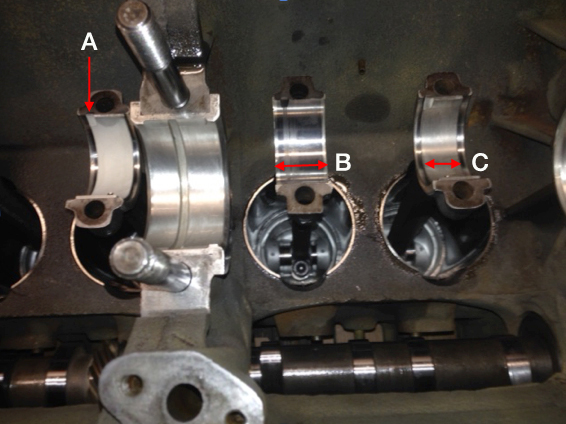
A Note Here On Rod Bearings:
There’s an MPJG engine in UK now running Peugeot 1.3 shell bearings. Tim Parrott has made this modification to TA2446 and successfully logged more than 2,000 miles so far. This was not a simple matter of dropping shells in and buttoning it back up however. The babbitt along with "a few thou off the conrods" is removed from the center of the rod and cap (B in the photo below) then a notch is machined in the rod and cap (A) to hold the bearings, as in modern applications. When fitted these shell bearings aren't quite as wide (C) as the babbitt had originally been and Tim retained the babbitt on the sides of the rods for use as a thrust surface against the crankshaft.
This engine is also using a balanced crankshaft and the last to be sold from a run of only five, having been sourced from Gosnay’s Engineering Ltd., Romford UK. These were a slightly improved versions of a Laystall balanced crankshaft (cracked unfortunately) loaned for the project by Brian Rainbow. At present I’ve heard no intention of their making any more. I should also mention here that the engine builder HAPPILY had NONE of the associated problems I had with the Phoenix TA crankshaft!
Tim Parrott photo
Peugeot Shell Connecting Rod Bearings
New Old Stock Pistons can sometimes be found for sale on eBay. Pistons fitting the MPJG engine were also used in Morris 10/4 Series III 1936/37 car engines (MPJM) but before purchase make certain they are for Series III Morris 10/4 cars. Reason being that the gudgeon pins for Series I and II (both side valve engines) sit lower in the pistons and at TDC will extend the piston above the top of the MPJG block! Just to confuse you more with this "Series" business the Wolseley 10/40 Series II engine (MPJW) also used 'our' pistons so beware which Series II engine you're discussing else you may find your pistons in your head.
And I'm told that F.W. Thornton in Telford, UK keeps a stock of TA pistons (JP brand from Australia) along with valves, guides etc. Their inventory lists +0.080” pistons, which may be their standard maximum over-bore for these engines. We’ve seen several using +0.060” over-bore and a smaller number using +0.080”. And yet there’s one TA in the USA running +0.100”. However, be on the cautious side here and have the block sonic tested by a reputable machine shop just to make sure that there’s sufficient metal left for each of the cylinder walls.
If you're searching just for Piston Rings try Thornton's or Cox & Turner in Yeovil, UK. Pistons and rings can also be custom manufactured as a set for reasonable costs in the USA from sources like Venolia, JE or Wiseco. And with a bit of research you should be able to find custom sleeves for a block if the cylinders are worn beyond oversized limits.
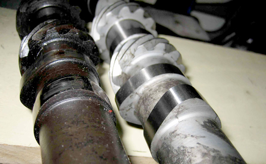
Ian Linton photo
Newman of Farnborough Cam On Right
New camshafts are available to order through Newman of Farnborough, Kent, England. When considering the timing gears do not re-use gears with sharp teeth! This is a sure sign they're worn out and your timing will never be consistent when using them.
The oil pump can be rebuilt using new gears or improved just by turning the spindle in the block by 180 degrees.
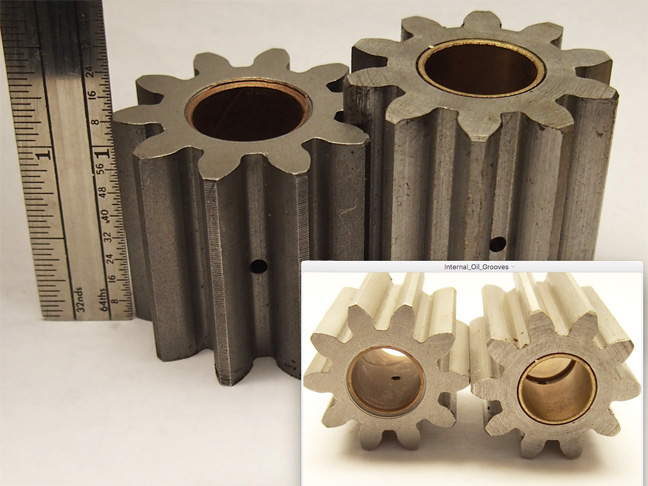
Oil Pump Gears
Pictured above are gears for a TA and TC oil pump. Except for the length they are identical. Both these were NOS and the only real difference aside from height is in the oil grooves inside the bushing which should be inconsequential. Since the shaft diameters are the same the TC gears can be machined and made to fit the TA oil pump. While on the subject of the oil pump and its function of supplying oil under pressure to the engine, here's a link to a Pressure Switch for the TA that when pressure drops to the 3-6 psi range both a warning light and buzzer goes off!
The original felt filter system could stand a bit of improvement. I used a Metro A series spin-on filter bracket and modified it to fit on the block. (See Modern Oil Filter in the menu.) This is not going to get you any points with a concours judge but it is a clean and economical solution to filter changes. However, do look at the Modern Oil Filter page to read about new filters which now fit inside the original Tecalemit housing.
Packing the pump with a viscous oil (some use Vaseline - I used Lubriplate 105 and motor oil) helps to prime it when you start the engine. I also filled the spin-on filter with oil then pressurized the system using a clean garden sprayer attached at the oil gallery until oil flowed from all the rocker arms. You won't be abel to do that, however, when using the Tecalemit housing. Choosing which oil to use for running in after the rebuild will occupy hours of happy research. If your cam is new or you've only resurfaced the lifters (as I did) or both, then you'll want something with a higher ZDDP count than most of the stuff off the shelf. I used Rotella T 30wt. for running in and the first two oil changes, switching to Rotella T 15-40wt. at 500 miles. There are now several grades of Classic 20W50 on sale for use in flat tappet engines requiring higher ZDDP levels.
Some owners of wet-clutch M.G.s have said that replacing the corks was not difficult for them and I gave it a try. But after spending too much time and not getting very far I chose to have it done professionally. Be sure to get the correct height of the cork (1/8") off the plate on both sides. (See Clutch/Flywheel in the menu.) I'm not sure what the minimum thickness is but if any corks are missing renew the lot. Another clutch factor to contend with is slippery additives in the motor oil. These clutches share the same oil with the engine and synthetics are sure to cause slippage. Steer clear of STP and similar synthetic products. There's also information on the Clutch/Flywheel page about using Kevlar instead of cork.
Considering the heavy weight of the flywheel several owners have lightened them in hopes of getting the engine rpms up faster. Actually its weight adds to the TA's ability to run smoothly at low speeds in higher gears. I decided to lighten mine by about 5 pounds (See Clutch/Flywheel in the menu.) and if there's a difference then it is hardly noticeable. However I'm using a 10 pound heavier than original crankshaft.
The HV3 SU carburetors are simple and easily rebuilt by the owner (making sure the butterfly shafts and body are not worn out) and they're also easy to tune once they're put in good condition. The SU fuel pump can benefit from having a Transil fitted across the coil. Better than earlier suggestions for transistorizing, it will reduce the arc between the points by about 80 percent. See the Fuel Delivery page for more info.
Needles for the TA & VA engines
This abbreviated Service chart gives the diameter of the TA carb needles in 1/4 inch increments measuring down from the shoulder. Needles from MG Type VA engines are included for interest considering that some TAs become Trials cars (Cream Cracker Team) using TPDG engines. These were, of course, for use with 'pool' petrol in a pre-war England. When nearing completion of my rebuild it was suggested that No.2 needles be used with today's fuel. I did so and have been satisfied with the car's performance.

New Viton Front Seal Conversion
The MPJG uses a felt seal in the timing cover at the front of the engine which is prone to weep oil. A seal kit is now available from Brian Rainbow, UK, consisting of a machined replacement carrier for the timing cover and a new Viton seal. Properly centered, it should eliminate virtually all oil leaks from the front. The MPJG does not suffer the rear seal leak that plagues XPAG owners. Brian also offers an Adjustable Oil Pressure Valve. I'm running both and consider each a worthwhile improvement.
A number of businesses offer water pump rebuilding. Select your rebuilder with care. (See Water Pump Repairs in the menu.) Inquire whether or not they are modifying the body of the pump. Some mods may render the pump no longer usable with the original carbon seal. Then again, the original seals are no longer available! Bob Butson, of Wales, has written a comprehensive article (Click HERE to view.) which details the disassembly and repair of his TA water pump. It is well worth reading and might just save you from destroying a reusable carbon seal.
One other thing regarding the water pump should be mentioned. It is advisable to replace the studs in the head, onto which the pump fastens, with bolts. Doing so will allow removal and replacement of the pump, and also the head, without having to remove the radiator. See the Water Pump Repairs page for more information on this mod.
The MG Octagon Car Club is a good source for many MPJG items and they have a parts catalog on their website. The club has undertaken short-run manufacture of a number of items, timing gears being among them. Be aware that parts are only sold to MGOCC members. However, at long last they now ship items to the USA. NTG also in UK is another source. They have gasket sets and a number of other items and sell on eBay. Other eBay sellers in UK stock engine torque straps, rocker shafts, pistons, rings and valves etc. Rebabbitting can be still be sourced in most larger cities by machine shops catering to classic and antique automobiles. Occasionally individuals will offer used MPJG items on eBay but understand how old these bits are. The likelihood of getting a 'like new' item is slim... but not impossible.
You'll need good set of Whitworth/BSF sockets and wrenches. And a torque wrench but be aware that there are no 'factory sanctioned' torque settings! Be sure to clean all the bolt holes using the proper taps prior to replacing or using new bolts. These are Metric threads and not Whitworth. BSF/Whitworth heads on metric fasteners... Mad Metrics! You'll need Taps and Dies of; 8 x 1mm and 10 x 1.5mm. New nuts and bolts can be sourced from Roger Furneaux in UK. Other items might be had through Doug Pelton, From The Frame Up, in USA.
And finally you’ll need a few books for guidance. These may actually be the first things you’ll want to get and I’d recommend them in this order.
1.) W. E. Blower's The MG Workshop Manual and Philip Smith's Tuning and Maintenance of M.G.s are both essential for understanding the MPJG.
2.) The Instruction Manual for the MG Midget (Series "T"); The handbook that came with the car.
3.) And a copy of The Spare Parts List for the MG Midget (Series TA and TB) will allow you to correctly identify a part when discussed with others.
4.) The T Series Restoration Guide by Malcolm Green deals with all the T series cars but also has sections on the TA.
Thanks to Ian, Brian, "Bob", Bob, Roger, Alan, and many others who offered help and advice on rebuilding my engine.
Contents of this Web Site are copyright © 2023
B Davis.