
Even before I'd begun work on the conversion I was prepared to make the necessary modifications to the block allowing the counterweight to clear the oil pickup; and the Phoenix rods to travel without making contact with the lower end of the cylinder walls. This is a well documented mod among MMM engine re-builders. What I hadn't expected was a series of deviations from original TA specs on the Phoenix crankshaft.
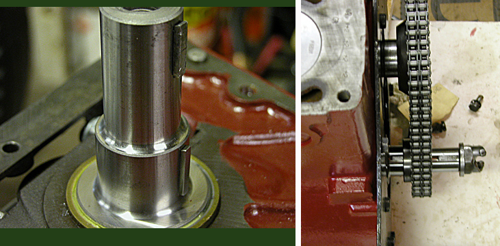
Left; crankshaft with keys inserted.
Right; the timing gear will not go onto the crank.
After installing the pistons and crank and torquing the rods and mains down I was ready to install the timing gears. I took my new (Octagon Car Club) gears with chain in place and tried to get the timing gear onto the shaft of the crank. Not only would the gear not fit onto the shaft but I also noticed that the two Woodruff key slots cut into the front of the crank, which drive the timing gear and the pulley, were not made to original specs. The slots are 5/32 inches wide... not 5 mm as on the original. Unsure where the problem was I tried the new gear on my old crank and it fit. The I.D. on the gear was correct. The diameter of the Phoenix crankshaft was wrong. Just wee bit too large for the gear to fit.
- Email To Phoenix- I'd written to Phoenix several months earlier asking for confirmation of the size of the little end bushings for their rods and if they knew of anyone I could talk with who had converted an MPJG engine for use with their crankshaft and rods. Phoenix replied with the little end specs but could not offer me anyone to contact who had carried out this conversion. When I discovered the difference in Woodruff key sizes from original I wrote to them again, explaining the problems I'd found and asking what size key I should use... and their thoughts on rectifying the difference. No reply followed. |
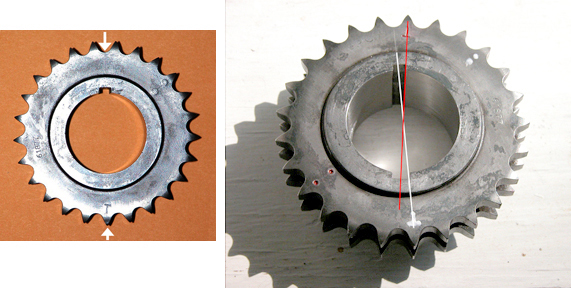
The new crankshaft timing gear before and after the broach.
Faced with either removing the crank and having the nose turned down and the key slots in the crank re-cut or modifying my new timing gear I chose the latter. Then came the choice of using their narrower, 5/32nd key, or make a stepped key (5/32 on the bottom and 5 mm above the crank). Not only would a new keyway have to be broached in the gear but because the diameter of the shaft was wrong (larger in O.D. than original) it would have to be honed out as well. This, of course would render the new gear useless for any "original diameter" crankshaft in the future. I chose to have the broach in the timing gear cut 5/32nds to fit the narrower slot in the Phoenix crank. And because the gear has an uneven number of teeth the broach could not be made at exactly 180 degrees but was made at 187.2 degrees; to correspond with the teeth and valleys of the gear as original. New timing marks were stamped into and painted on the gear. The white line on the photo represents the 7.2 degree move off 180.
This left the issue of what to do about the 5 mm key slot in the pulley.
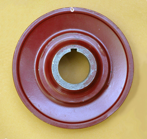
The pulley, being a much softer metal, I found had been distorted somehow. Perhaps from over tightening at some time in the past. It was actually wider by .009" in the center of the hole than on each end. And not wanting to upset it any more than necessary I chose to use a stepped key, taking advantage of the larger surface area of the original 5 mm key to lock it in place. Just as important, this would keep the timing mark of the pulley in the correct spot for static timing of the engine. Re-sleeving it to straighten the hole and then broaching the sleeve was considered but because of the amount of metal that would have to be removed, severely weakening the pulley, the idea was dropped if favor of the stepped key. The stepped key was made from one of the old 5mm keys by taking the same amount off each side to keep in centered. The two discernible keys can be seen in the first photo at the top of the page.
I thought the ordeal was over. It was not.
After the problems with the nose of the crankshaft were sorted out, the bridges put in place and the end plates attached to the block I was ready to install the flywheel. Then I find the Phoenix crank is a bit greater in diameter across the base than the original. And to fit the flywheel onto the Phoenix crankshaft metal had to be removed from the flywheel. (Another item now made questionable for future use with an original crankshaft.)
Once I could draw the flywheel tight against the rear flange of the crank I discovered that the dowel holes -through which tapered pins are driven from the outside of the flywheel and which align the two, were not tapered as on the original crank, but drilled straight. This required making new pins which were tapered so they'd wedge tight when they passed through the flywheel but become straight when they enter and fit snuggly into the crankshaft. Fortunately the hole in the crank was the dia. of the small end of the taper in the flywheel. The way things are going it could just as easily have been the dia. of the large end of the taper in the flywheel. Envision that!

Recess in the Phoenix crankshaft are not the same as those cut into the original.
While dealing with the tapered pin problem I had a closer look at the original crank and found another inconsistency between the two. This one involves the location of the first motion shaft pilot bearing. The bearing seats against the upper recess in the back of the crank. The recesses in the end of the Phoenix crank are not cut as deeply as those in the original crank and therefore does not allow the bearing to go as deeply into the center of the crank as it should. Careful study of the photos above and drawing below show these differences. The cuts into the cranks are represented in red on the drawing below.

So that I could visualize the differences in the two crankshaft ends a split drawing was made to scale. The Original crank (with deeper cut) is on the top and Phoenix crank on the bottom. The drawing also shows the placement of the Center for the Spigot bearing, the Bearing itself (right, against the red) and Cork clutch.
The Center for the first motion spigot bearing has three pins with springs onto which the cork clutch plate fits. (Only one is shown, top and bottom, on the drawing.) The clutch plate is held against the springs with a large circlip. The spring's function is to move the clutch plate off the flywheel when the clutch is engaged. This Center determines distance the Cork clutch plate is from the flywheel and as you can see the clutch plate is now moved aft a fraction of an inch.
With the shallower cut in the Phoenix crankshaft the Cork clutch plate must be pressed further forward by the pressure plate to engage the flywheel. The dimension here is small, only an 1/8 inch or slightly more but this puts a much greater compression load on those three small return springs. They're less than half an inch long to begin with! And because the crankshaft depth is not as it should be normal use may end up destroying the springs (or the Center) altogether. Only time will tell.
The next page, Phoenix Three, deals with piston pins, their teflon buttons and a summation of my Phoenix experience.
| Phoenix One | Phoenix Three |
Contents of this Web Site are copyright © 2020
B Davis.