FROM THE TANK TO THE PUMP
The TA (and TB) are unique to the other T-Series cars in the way they deliver fuel to the pump. As the P and J-Types before them, the TA has two separate supply lines leading from the tank to the bulkhead where they meet at a 3-way petcock. One line serving as a main supply while the other is the reserve. Turning a knob on the dash/facia actuates the petcock selecting the desired line.
MAIN / RESERVE KNOB ON THE FACIA
Clockwise for Main Supply | Counter Clockwise for Reserve
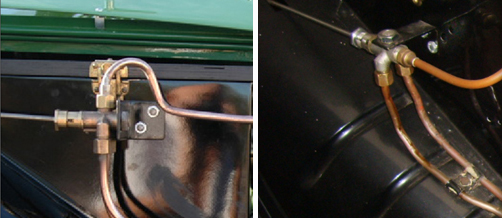
Early (left) and Late (right) petcocks.
Two different petcocks were used on the TA. Early production cars, those up to and including chassis No. 0823, employed a petcock mounted at its forward end. Beginning with TA0824 the mounting bracket was rotated 90 degrees, moved rearwards and the petcock affixed at its top. Examples of the two are above.
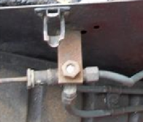
Mysterious Holes
An interesting note here is that even after changing the location for the petcock bracket at TA0824 the Works continued to receive and use bulkheads drilled for the early cars. Clearly visible in the tool box above (TA1395 in unrestored form) those holes were still present on cars with chassis numbers beyond TA3000.
Were they present on the TB as well?
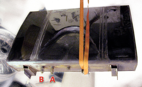
FITTINGS AT THE TANK
The main line (A) has a short section of pipe extending upwards into the tank. All the fuel above it serves as the main supply. Once the level of fuel falls to the top of that pipe air is drawn into the line and the pump will tick madly away. There should now be about 3 gallons left in the tank and switching the petcock knob from "M" to "R" allows fuel to be drawn through the reserve line (B). This fitting is almost flush with the bottom of the tank and there is a fine mesh strainer extending above to help filter the fuel entering the line. Once this fuel finds its way past the petcock the pump should soon resume it's normal ticking.
Also visible in the photo is the fuel drain plug to the right of (A) and near the center of the tank.
MG TA/TB FUEL PIPE ROUTING
By Clive Sherriff - Oxford England
The following is the route taken by the fuel pipes on the TA and TB model MG. The description has been verified from factory and period photographs, and from actual observation on a number of cars, and principally on two unrestored cars, MG TA Chassis No TA 1316 and MG TB chassis number TB0487
From the tank, the centre most pipe (Pipe A) loops down from the tank union with a 1 ¼ inch radius, and goes straight forwards to the front of the car, just to the rear of the shock absorber mounting chassis cross bar, where it bends to the passenger side of the car with a 3 inch radius to rise slightly and pass above the near side (i.e. passenger side) side rail of the chassis. Also at that point, Pipe A passes over the other fuel pipe (Pipe B) which comes from the outer tank connection union, but runs just below Pipe A as they cross the car. Pipe B follows a similar course, going under the Pipe A where they cross over the top of the chassis and along the chassis rail below Pipe A.
Both then run along the outside of the chassis rail in line with the chassis to the first securing point of a double set of clips level with the rear bar of the battery holder frame. Both top and bottom clips are J section, both secured by a single 3/16 inch round headed screw, with a washer and nut on the inside of the chassis rail. The Pipe A from the central tank union is the upper pipe.
Both pipes then pass through the holes in the spring outrigger, and are again double clipped 6 inches forward of the point they pass over the spring outrigger centre line.
The next double clip is 9 inches to the rear of the Handbrake Cross Shaft, the next 3 inches in front of the Handbrake Cross Shaft.
The pipes then go through the front body outrigger holes, and 6 inches in front of that outrigger are the pipe unions……..
…….before the pipes loop up, between the chassis bulkhead stay, and to the inside (engine side) of the chassis mounted bulkhead stay and the bulkhead foot plate panel.
At this point the pipe from the central tank union (the upper one along the chassis side rails – lets call it "Pipe A") becomes the one on the most nearside route – the other being more to the centre of the car.
Both pipes go up, close to the bulkhead, pass over the radiator stay, but UNDER the grease nipple chassis lubrication bracket (on later TA and TB) and curve with about a 3 to 4 inch radius, to run along the bottom of the toolbox. At this curve, Pipe A becomes the uppermost. The pipes are held at this side of the toolbox, just above the outer two of the three holes in the bulkhead, by the ubiquitous two clips….
……and again about 4 ½ inches from the other end of the toolbox are another pairs of clips.
Then the pipes curve back and follow the bulkhead toolbox line (not straight up towards the fuel tap) with a tight 1 ¼ radius on the upper (now inner) pipe A from the central fuel tank union, and a larger 3 inch radius on the lower pipe. Pipe A is closest to the tool box here and by this time they are both effectively at the same level. Beneath the fuel tap they curve up on a 3 inch radius and connect to the fuel tap.
Fuel Starvation Problem
A few years ago I had an annoying problem with fuel starvation and blamed it on the pump. I'd rebuilt it but still on occasions when laboring up steep hills, especially on hot days, the engine would begin missing and then overheating till I'd pull over with a few choice words and wait while it ticked away till the float bowls filled with enough fuel to continue.
I considered vapor lock but I've never had that problem and so kept blaming the SU pump or my lack of properly rebuilding it. After procrastinating for months I decided to tackle the problem head on. It turned out to be so simple that I felt foolish not to have considered the culprit earlier. Bench testing it wet proved the pump worthy. However, when replacing it on the car and having it pump fuel from the tank into a container, it delivered fuel but also produced LOTS of bubbles. Ah Ha…! Somewhere air was getting into the lines. The copper lines showed no sign of weeping at connections or indication where air might be drawn into the system so the only other (and obvious) place it can happen on a TA/TB is the Reserve Petcock. I removed everything inside the petcock valve and covered the open end with my hand (this allowed the pump to pull fuel through both lines) then I switched on the power and the pump delivered the fuel into my container without bubbles. This confirmed what I suspected …air was being introduced at the petcock.

Thanks to Jeff Redman for the original drawing.
In normal operation the cork (B in the diagram) around the valve should seal the petcock but that wasn't happening completely so the solution that worked for me was to install an O Ring fitted at the rear of the switching mechanism, inside the petcock. It was a tight fit but no more bubbles and I've had no excessive ticking under the above driving conditions since.
Note: Regarding Petcocks leaking fuel or allowing air in; From The Frame Up sells a brass valve (to fit inside the body of your petcock) which uses two O-rings instead of cork to seal the unit. And somewhere I've read that Teflon has been used instead of the cork possibly solving any air leak permanently. Sounds like a good idea too.
SLOW RUNNING CONTROL
Although more a function of the mechanical side of fuel delivery there is the interesting Slow Running Control. The knob is under the oil pressure gauge, last on the right, on the metal panel and its function is to adjust the idle speed of the carbs as the engine warms enough to run without the use of the choke. It is threaded inside the housing and operates more like a bolt in a nut than the pull-out starter and mixture control knobs.
Turning the knob retracts the wire attached to the lever. Then as the lever lifts it catches an arm on the butterfly spindle increasing the rpm. The spring, fitted at one end to the bracket for the air cleaner and the other at the end of the actuating lever, is used to help the lever return home. As the engine warms the knob should be screwed back to the normal idle position.

Slow Run Control Knob Far Right on the Facia Center Panel

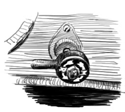
Spring Attachment to Control Lever
The illustration above, looking up from between the carburetors, shows the Slow Run wire coming through one of the holes in the bracket and attaching to the lever. The return spring goes into the other hole in the bracket, makes a loop and attaches to the other side of the lever.
External Fuel Filters
In-line filters are not recommended but if they are installed it should not be before the fuel pump. If the supply of fuel becomes blocked before reaching the pump it can cause the pump to overheat and damage the coil. There are two separate screens that fuel must pass through after it leaves the tank. One in the fuel pump and another at the banjo fittings at the top of each of the fuel bowls. These should be sufficient to keep debris from entering the carbs. If the supply of fuel is so contaminated that either an external filter is considered or these screens are being blocked then the tank should be repaired or replaced.
SU Fuel Pump Transil Modification
For quite a while it was suggested that 'transistorizing' the fuel pump was a better method for reducing the arc across the points (..which eventually eats away the contacts, causing the ticking to stop and us to bang on the thing with a metal object to get it ticking again!) than the capacitor the Works introduced in the MGA era. Transils are far better. Current day testing reveals that a Transil will reduce this spark by 80% with no loss in the function of the pump. Read Eric Lembrick's article in TTT2 on extending the life of your pump. Read also the comments which follow that article if you are a DIYer.
Peter Cole, UK, supplies Transil Kits already made up with instructions. You will find contact info at the end of his article The SU Pump Revisited, Issue 73 TTT2. If you do the modification your self Transils can be sourced from various vendors online.
A word of caution if you are unsure of Earthing on your car or if you have a Positive Earth car that you 'might' one day like to convert to Neg. Earth; make sure you get the bi-directional variety of Transil so as the pump will continue to work in either Positive or Negative Earth environment.

The Transils I bought have leads long enough on each side to loop around and make an 'eye' (soldered to itself) for the two screws involved. |