
As daunting as it may seem, the TA gearbox is not difficult to strip down and reassemble.
The following instructions were interpreted from a T Register Rebuild Seminar given by Brian Rainbow, UK and closely follow those in the W.E. Blower Workshop Manual.
First thing to do once it's out of the car is clean the outside. If it's been in use for several years it will be a messy job but gasoline works well in lieu of a parts washing machine. Drain the oil if that hasn't been done, put the box in neutral then remove the remote shifter cover and the bell housing. Wash out the inside with gasoline or degreasing solution getting as much of the shiny filings out as possible. Remove the prop shaft drive flange, unbolt and remove the rear casing, including the speedo drive. And be kind to Mother Earth.. recycle... don't dump that crud behind the garage, please.
Remove the locking wires and set screws on all three selectors. Tap out the selector rods to the rear, starting with 1/2 gear selector, then 3/4 and finally reverse, taking care to catch the 5 balls and 3 springs (the detents). Note their positions and remove the 3 selector forks. Rotate the main shaft and locate the spring-loaded pin. Depress it and rotate the locking ring. This will allow the gear to slide on the main shaft. Then remove the main shaft, complete with bearing and gear cluster through the rear of the gearbox casing.
Now remove the layshaft dowel bolt from under the gearbox, drive the layshaft spindle out using an undersize drift or long punch. Let the layshaft gears rest in the bottom of the gearbox. Remove the circlip on the front of the first motion shaft and tap the shaft into the gearbox to remove it. The layshaft gears may now be removed from the bottom of the box. Take care that the two needle bearings and spacer inside the laygears don't get misplaced.
From the left side of the case remove the dowel bolt which locks in the reverse gear shaft. Using a bolt (the shaft has threads in the end), extract the reverse gear shaft from the case. (When replacing this shaft remember you'll need to rotate it till the hole lines up for the dowel bolt.) Reverse gear may now be removed. Remove the front bearing from the casing and press the rear bearing off the main shaft. And there you are!
For another take on the same subject see the fine article by Rick Storms, Rebuilding The TC Gearbox - An Overview. These boxes are very much alike with the exception of the first motion shaft.
Don’t make this mistake:
This may be obvious but I’ve seen what happens if you wash out the inside of the transmission case and gears with gasoline or engine cleaner/degreaser and then set it aside for a long period of time. All inside the case will rust just from moisture and you will be in a worse place than if you had done nothing and left it oily.
Reassembly
Thoroughly clean the case of any gear filings with a solvent and then either steam or pressure wash out the inside. Examine all the bits and clean the bearings. If when cleaned and dry any of the bearings sound scratchy or are dragging when spun they should be replaced. If in doubt or there's been problems with or excessive noise in the box then replace them as a matter of course. Finding new replacement gears is not in the cards. Finding another used gearbox complete may be possible. They're pretty substantial boxes and you're likely to be okay with bearings alone. Lightly chipped teeth can often times be cleaned up using emery cloth. Some owners like to paint the inside of the case and now is a good time to do that. Glyptal is the paint of choice for most.
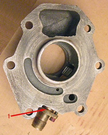
Replace the roller bearing for the first motion shaft into the case making sure to include any shims in front of the bearing that you may have removed during disassembly.
Replace the Reverse gear shaft (1) through the gears (2) into the case while making sure the hole in the shaft lines up with the locking bolt hole on the left side of the case. The smaller gear faces forward. Replace it's locking bolt.
Then, (with both needle bearings and spacer tube inside!), place the laygear (3) into the bottom of the case. Do not replace the shaft inside it yet otherwise the first motion shaft cannot be installed.
Now install first motion shaft (4) above.

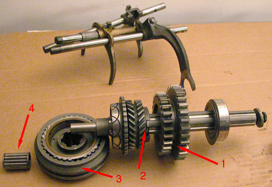
If the rear roller bearing (2) (with shims (hidden behind bearing)) was removed it will need to be pressed back onto the case now. Shims go on first!
Next, replace the first motion shaft (1) through it's bearing in the front of the case (2). The shaft will have to be driven/pressed through the center of the roller bearing. I used a long, soft-metal rod which extended through the rear of the case and was centered inside the rear of the first motion shaft (where the needle bearings at the front of the main shaft run) and tapped the shaft home with a heavy copper hammer.
Replace the big 'stepped washer' cover (3) (if it has one). The 'indented' center portion goes inward (toward the rear).
And then replace the locking ring (4).
In the background can be seen the three selector shafts. Keeping up with them is much easier if they're loosely assembled -in order- and kept together as a 'set'.

Now insert the laygear's shaft (1) from the rear of the case and through the roller bearings and spacer of the lay gear. (Keep in mind the hole in the shaft must align with the locking bolt hole in the bottom of the case.)
Here you will need to lift the lay gear to line it up with the incoming shaft. Use a small dowel if it helps being mindful that you are meshing with the gears on the first motion shaft above it.
Once in place make sure that the gears are freely turning. Now lock the lay gear shaft with the locking bolt (2).
Two of the detent balls live in a 'tunnel' here (3). More about this below.
By the way, Rick Storms built a nifty little cradle to set the gear box in while assembling/disassembling. See the link by his name above.
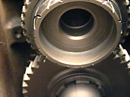
The main (or third motion) shaft is next but first put the needle bearing into the rear of the first motion shaft. No bearings are shown here yet, only the hole in the back of the first motion shaft where they go. The same hole into which the soft metal dowel was centered in and used to drive this first motion shaft into the bearing on the front of the case.
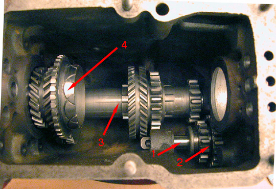
With the spacers and rear bearing on the third motion shaft and all gears removed bring it in from the rear of the case and begin to slide it through the gears onto the splines one at a time in the order shown above. Before getting too far along place the needle bearing (4) into the end of the first motion shaft.
The synchromesh sliding dog will have to be in place over the cones as the shaft nears home. And the locking ring tab is also engaged as the shaft travels through Third gear. Take care to assure third motion shaft enters the needle bearings gently in the end of the first motion shaft.
First / Second gear (1) (the smaller gear faces the front!), then Third (2) (with it's locking ring tab and synchromesh cone.) And finally the synchromesh sliding dog (3) for Third and Fourth gear. The needle bearings are for the front of third motion shaft (4) having already been placed in the rear of the first motion shaft.
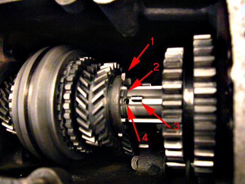
The view above shows the indent for the locking ring with spring loaded pin. Third motion shaft is being inserted and almost home.
For photo purposes the pin (3) is lying in the spline of the main (third motion) shaft and the shaft has not been fully inserted into the needle bearings of the first motion shaft.
Third gear must mesh with it's counterpart on the lay shaft as the main (third motion) shaft is being installed.
The spring (4) can be seen inside the hole. Once inserted into the hole, the pin is pressed down with a small screw driver while the shaft is pushed forward through the splines.
When the locking ring tab (1) can be rotated in the grove (2) rotate it to lock the gear in place.
To this point the rear bearing has not engaged the case and the shaft is easily pushed into or pulled back out of the case.
Finish by driving in the third motion shaft and it's bearing into the case taking care fitting it into the needle bearings in the first motion shaft

Before inserting the springs, balls and shafts the bronze selector levers should be placed into their prospective grooves in their gears.
There are three springs and five balls for the selectors shafts. One ball and spring for each shaft The extra two balls sit between the shafts. They keep the gear selector from operating but one shaft at a time. No springs are found in the horizontal tunnel - just the steel balls.
Now begin by inserting a spring and then a ball into the top of either side hole. (I found that a chop stick with a 'cup' dished out of the end worked well. The 'cup' was made by twirling a drill bit against the flat end of the stick.)
Using this 'tool' depress the ball down into the hole until the selector shaft can be inserted far enough to keep the ball in place while the tool is removed. Once the tool is out cover the holes on the side and top with your finger just in case the shaft doesn't continue and the ball tries to fly out. You'll get the hang of this very soon.
Push the shaft on through, past the threaded hole in the center lever and to the front of the case while keeping an eye on the hole on top of the shaft that locks the lever to the shaft. You'll feel the click as the shaft passes over the indent. When the threaded hole in the selector lever lines up with the hole in the shaft the locking bolt can be screwed in. You might have to tickle it into position with a small probe.
Once the first shaft is in place insert a ball into the horizontal hole between it and the center shaft. The ball must be able to go into the indent of the first shaft before the center shaft can be installed.
The center shaft is next. Repeat the step where the 'tool' is used to compress the ball and spring into the hole while the shaft is installed. Once the shaft begins to emerge from the selector lever slip the spacer on the shaft then continue pushing it home (you'll feel the click) till the locking bolt hole is visible in the selector lever. Now replace the locking bolt.
Place a ball in the horizontal passageway next to the center shaft. And then insert and compress the last spring and ball into the hole. Run the shaft through the hole in the center selector to the front of the case and align the locking holes as before. Again you'll feel the click of the ball into shaft indention. Replace the locking bolt.
Try out the shifting before wiring the locking bolts or putting the box into a car! This is most easily done by temporarily installing the remote on top of the box and making a dry-run through the gears.

The indention of the selector shafts (1) can be seen on the right. The detent balls pushing into these indentions are what gives the feeling of resistance, gives that 'clicking' feel from one gear to the next and keeps the gear engaged.
In operation, the synchronizer sliding dog (2) is pulled onto a brass cone (hidden here but seen in photos above) which slows rotation of the first motion shaft and allowing the gears of the dog to mesh with that small row of gears (3) quietly.
The selector nearest the camera is for reverse.
Close up the rear of the case by replacing the rear engine/transmission mounting plate. (Not shown) and the rear cover plate.
Gaskets go between the case and the mounting plate and another between the mounting plate and the rear cover. There was no gasket between the speedometer gear mounting and the rear cover (1) so I used only gasket cement here.

Finally comes the spacer (1) and the prop shaft flange. The prop shaft flange has gears for the speedometer (2) and a reverse cut 'gear' (3) for returning any oil that might have made it this far. After the spacer tap on the flange using a soft hammer till it bottoms out. Now replace the washer (4) with the 'knob' toward the splines, the lock washer and finally the nut.
Make sure the locking bolts are snug and fitted with wires and also the two screws attaching the speedo gear into the rear plate and you're finished.
Time now for a brewski.
What Was Not Discussed
The synchromesh sliding dog break down.
No banjos please.
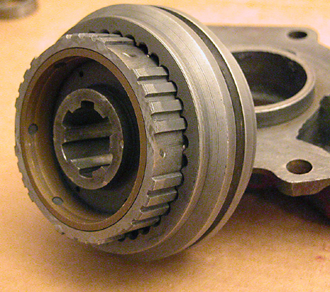
The synchronizer dog consists of an outer 'sliding' gear on an inner gear. Located inside the inner gear are 6 springs with balls pressing upward toward the outer gear. Two of the balls can be seen here just peeking from under the outer gear.
Removal (and replacement) of the balls and springs can be very exciting if little forethought is given. The easiest method for disassembly is to place the gears in a bag such as a pillow case and using the thumbs and heals of the hands press the outer gear off the inner one allowing the balls and springs to fly out yet be contained. For reassembly I use a tool made from a radiator hose clamp -the screw type- which is about a half inch wide and large enough to go around the perimeter of the inner gear. Into the solid part of the band I drilled a hole large enough for one of the balls to pass through the clamp. Tighten the tool leaving it just loose enough to allow you to twist it around the circumference of the inner gear. Locate the hole in the tool over a hole in the inner gear. Insert the spring followed by the ball. Twist the clamp tool toward the next hole and repeat. The clamp tool keeps the balls from flying free while you finish the round.
Then VERY CAREFULLY use the outer gear to push away the clamp tool.. moving it off the balls leaving them compressed and in between the gears where they should be.
Rick Storms (see link above) and Bob Butson have a similar tool with which to replace the springs and balls.
Click here to see Bob's Method of Inserting Balls Into a TA synchro Hub.
Other than cleaning, there is little use to separate these parts unless you suspect a problem with the springs.
